yeah definitely a problem in first gear.. tried the drilled out solenoid and the standard one... first gear is definitely a problem if you hit it hard... it scares me over boosting the engine... I back off as soon as it happens though.. but no question about the differences in second gear... drilled out solenoid and the standard restrictor and something like that map posted above... however I wish there was something I could do about 1st gear... maybe that is just a trade off with a 2 dimensional graph... however if we could plot it against load... different story ??
any chance of a bench test Pete ?
boost control using nistune experiences anyone ?
Moderator: Matt
-
Legionnaire
- Posts: 125
- Joined: Fri Oct 03, 2008 5:45 am
- Location: Moscow, CFD, Russia
I think i'll post here.
First of all i would like to thank you for all your boost control research and all that time you spent figuring out BC capabilities and posting results in here.
Second, about boost spike on the first gear - I think that events are happening and environment is changing a little too fast on the first for stock boost control system to keep up with it. You can try making your map load dependent in the spiking area - this may help. I don't have any first hand experience with BC on s15's, but i do with er34's and even with different boost controlllers, including AVC-R and the such, and even with the fastest feedback speed set on them i was unable to eliminate 1st gear boost spike completely without resorting to some measures like two stage boost/lowered solenoid start duty. But i think that it is not a major issue - like Pete said you can not load up your engine enough to damage it and VE is dropping after peak torque RPM point anyway, so i would not bother.
As for hitting fuel cut - have you removed it from TP limit vector? I'm asking this because when i did it to my r34 and then found that fuel cut was still there when i reach 1-1.05 bar IMP, i was shocked. I thought that i had missed something or done something very wrong. It came out to be pressure referenced cut, not MAF voltage cut.
Cheers, Petros.
Last edited by Legionnaire on Wed Dec 17, 2008 11:28 am, edited 1 time in total.
Cheers,
Petros Katunian
Petros Katunian
-
chris2712au
- Posts: 343
- Joined: Thu Jun 19, 2008 1:52 am
- Location: sydney australia
point taken.. however I might give some more things a try... everyone feel free to jump in on this one..
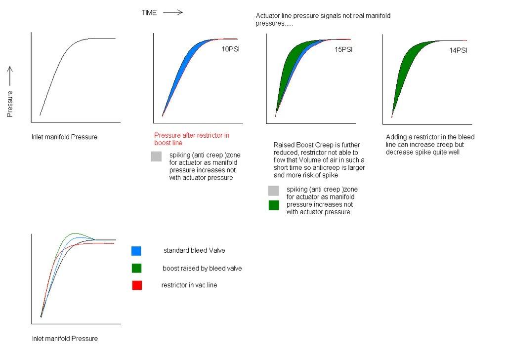
the facts as I see them anyway..
1. restrictor
a) the restrictor itself is an anti creep device as it slows down the amount of pressure transferred to the actuator side... Ultimately they will become equal but the actuator will be behind the boost signal..
2. Boost line
a) the boost line to the boost solenoid / bleed valve can be lengthened or increased in diameter to give less wastegate creep... even a mini tank can be used and tuned like a catch can just for a more room to store the boost signal..
3. Boost control device
a) bleed can be introduced to decrease creep and is also used to lift the maximum boost level.. however the more you increase the boost in the top end the more chances you have of spiking ( comon with standard bleed valves)
4. Actuator
a) the actuator can be pre-loaded through packing the bracket out or adjusting the actuator linkages.. this increases wastegate cracking pressure so raises the maximum boost but is prone to wastegte creep still.. although the more pressure on the actuator linkages means that it will need more air to reach the desired pressure to open so in a way it can reduce creep minutely. Also note that a wastegate actuator that does not have a strong enough spring can creep naturally cause the exhaust gasses aid in pushing it open rather than the wastegate pushing the gasses back to keep generating boost..
so why does nissan put a restrictor in the vac line to the solenoid ?
a) to limit the maximum amount of bleed so in first gear where you can get max boost quicker the jets will govern the amount of feed / bleed to prevent spike... This is why the free boost mod tends to spike...
why are turbo tec designs able to work well ? (gated tees)
well I guess it is all about how fast the wastegate can react.. The gated tee as compared to a restrictor is able to crack open and then the further the pressure pushes it back the more it can flow... differing from the restrictor where it is one size hole that's it... so it is able to stop the boost signal from reaching the actuator by spring pressure and able to transfer it quite rapidly once the seal cracks open... ist and second gear boost levels are much the same... could we program it... well I am going to plumb in the bleed as well just to see...
what else could we try..
Well maybe an after market solenoid that is able to handle alot more pressure than the stock one and flow a much more eliminating the need for restrictors and the like... however it would have to be impedance checked by pete so the output transistors dont get fried on the boost control..
Get a blitz EBC and actually control boost from boost pressure... although even still they may spike..
Pete... How is graemes car in first gear....is it spiking ?
Hey Chris,
I gotta say I'm impressed by the depth you've dug into this boost control subject!
But I'm not feeling it on the first gear stuff though. I see it as prettty much irrelevant because:
1) Normally you won't get a lot of boost in first gear because of the minimal load on the engine.
2) Whatever boost you can get will generally result in crazy wheelspin anyway - so you really need to try and minimise this by modulating the throttle.
3) It all happens so fast that no system is going to realistically catch all of the spike.
But I agree about the jets restricting airflow to the WG actuator - which means that it will take longer to react. I suspect this is why the better EBC's run their solenoids in series. So no jets required.
I suspect Nissan run their system using jets because it offers a good failsafe mode - if the solenoid dies you won't get an uncontrolled boost condition.
Hey, here's a thought for ya. I don't see any reason why you couldn't plumb the OEM solenoid in series. Then turn you boost control maps upsidedown. So the valve starts off fully closed - giving best possible boost response. The moment boost comes up you increase values in the maps to open the solenoid and knock boost back to where you want it. This would have the added side-benefit of getting rid of all jets.
Hmmmm. Maybe an idea to play with over Xmas...
PL
-
chris2712au
- Posts: 343
- Joined: Thu Jun 19, 2008 1:52 am
- Location: sydney australia
yeah guess I am kind of persistent.. what I have been playing with is the early values in the map as I had posted... By Bleeding off in the early stages off boost... what results is a much more powerful mid section might not look like much on the dyno but on the street... for sure... and especially noticeable in second gear... however those little restrictors seem to give the same response rate no matter how fast the boost increases the wastegate is taking the same time to react... so if you bring on the boost fast in first it will spike by a couple of PSI.. when you are running on the limit for second gear in the high 4v.. the spike in first is 17PSI enough to fuel cut... I can bring on the boost slower and get around this spike.. but it is much more fun to get the mid pumped up... it was giving me great fuel economy too.. as there was no need to floor it.. the mid was plenty powerful enough...
I find that even the turbo tech type gated tees will creep as well
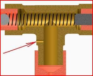
see the little hole ? this is so the wastegate can close when the ball spring is shut.. problem is when it starts maxing out the boost drops off in the top end... and well first thoughts was to open it up because of my bigger actuator... second thought was why not make it variable hopefully control the top end..
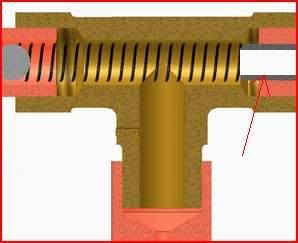
hole is blocked off and moved into the adjustment screw that is plumbed into the boost control solenoid.. playing around with that hole gave for some interesting results.. cant wait till I get to program it.. theory is to use the gate for the anti creep and just use the bleed for top end..
Benefit is you dont have to bleed a heap of boost and the reaction time of the sprung ball gate will out perform any EBC you can get.. the faster the reaction time is the more we can stop spike and bring boost on..
I guess what I am trying to say is that say on a map of 65.. there will be a slight positive pressure on the wastegate... this will help the exhaust gasses push it open early a simple check i did was to watch the point of when the vac turned to boost... it varied substantially when adjusting higher values in the first two rows and it was so noticeable in the driving.. although max boost was still reached at about the same rpm looking at the curve it was not diagonally increasing it was more like an "S" shape.. once again in second gear... then in first it was a no brainer.. yup wheel spin @ 17psi and then fuel cut..
as for the inline approach and turning the maps upside down interesting I did think of it... just come up with 3 points...
1. reaction time again... of the ECU and PCM valve
2. strength of the PCM valve spring to fight the boost signal ( I will pressure test @ 20PSI for good measure)
3. when solenoid closed where will it vent to so the wastegate can close ? it may lock up..as air will have to travel in both directions through the valve.. do the expensive ones have a vent also in the solenoid ?
If it could flow both ways then makes for a good fail safe too unless it jamed shut... guess it would be good for power to close... not spring so if it crapped itself it would only boost to the maximum of the actuator setting.. pitty it is power to open... but hey with a small ecu mod that could be changed... well I think ? and then keep the maps the same ?
how does the apexi one do it ? wouldnt mind seeing one of their valves..
but I like the way your thinking..
as for an update well this mod to the turbo tech is in my car.. it drives really well I have the mid section of a map thats tuned for 15PSI... but only on 13 PSI... as I am leaving room this time for the spike so I can measure it without fuel cut the aim is to hold 13 all the way.. if possible then bump it to 15... as long as 1st behaves itself.. but even now no traction in first... so results will be hard to measure... but I am not happy with second gear yet..
will keep posting and hopefully have a map up soon..
I find that even the turbo tech type gated tees will creep as well
see the little hole ? this is so the wastegate can close when the ball spring is shut.. problem is when it starts maxing out the boost drops off in the top end... and well first thoughts was to open it up because of my bigger actuator... second thought was why not make it variable hopefully control the top end..
hole is blocked off and moved into the adjustment screw that is plumbed into the boost control solenoid.. playing around with that hole gave for some interesting results.. cant wait till I get to program it.. theory is to use the gate for the anti creep and just use the bleed for top end..
Benefit is you dont have to bleed a heap of boost and the reaction time of the sprung ball gate will out perform any EBC you can get.. the faster the reaction time is the more we can stop spike and bring boost on..
I guess what I am trying to say is that say on a map of 65.. there will be a slight positive pressure on the wastegate... this will help the exhaust gasses push it open early a simple check i did was to watch the point of when the vac turned to boost... it varied substantially when adjusting higher values in the first two rows and it was so noticeable in the driving.. although max boost was still reached at about the same rpm looking at the curve it was not diagonally increasing it was more like an "S" shape.. once again in second gear... then in first it was a no brainer.. yup wheel spin @ 17psi and then fuel cut..
as for the inline approach and turning the maps upside down interesting I did think of it... just come up with 3 points...
1. reaction time again... of the ECU and PCM valve
2. strength of the PCM valve spring to fight the boost signal ( I will pressure test @ 20PSI for good measure)
3. when solenoid closed where will it vent to so the wastegate can close ? it may lock up..as air will have to travel in both directions through the valve.. do the expensive ones have a vent also in the solenoid ?
If it could flow both ways then makes for a good fail safe too unless it jamed shut... guess it would be good for power to close... not spring so if it crapped itself it would only boost to the maximum of the actuator setting.. pitty it is power to open... but hey with a small ecu mod that could be changed... well I think ? and then keep the maps the same ?
how does the apexi one do it ? wouldnt mind seeing one of their valves..
but I like the way your thinking..
as for an update well this mod to the turbo tech is in my car.. it drives really well I have the mid section of a map thats tuned for 15PSI... but only on 13 PSI... as I am leaving room this time for the spike so I can measure it without fuel cut the aim is to hold 13 all the way.. if possible then bump it to 15... as long as 1st behaves itself.. but even now no traction in first... so results will be hard to measure... but I am not happy with second gear yet..
will keep posting and hopefully have a map up soon..
-
Legionnaire
- Posts: 125
- Joined: Fri Oct 03, 2008 5:45 am
- Location: Moscow, CFD, Russia
Well, apexi boost control solenoid is dying on one of my friend's car. I'll ask him for permission to dismantle it and to see its internals. But I am pretty certain that it is nothing more than either a swing or less likely a poppet valve that "swings" between two ports, connecting them to the third port. It either vents a part of the compressed air to the atmosphere from a wastegate signal line (in single port/integral wastegates) or adds some pressure on wastegate diaphragm against WG spring (on dual port/external wastegates).
I'm not sure as to how boost jet works in our case. What kind of "event" does it add and how sholud we evaluate it? Is it the pressure restrictor, like oil pressure restrictor, i.e. there is a permanent pressure drop after it, or is it a delay in the pressure wave that travels from intake manifold to wastegate? Is pressure drop fixed, say, 1mm jet causes 5psi output pressure with 7psi input pressure, or is it pressure dependent, like 2psi drop @ 7psi input and 5psi drop @ 30psi input? how does it work when intake manifold experiences depression - is it the same fixed drop acting in reverse, i.e. -5psi output with -7psi input?
Some boost control related off-topic, if you dont mind
I often see that aftermarket EBC instructions recommend to keep signal line length to a possible minimum. I'm not sure why exactly this is so, because i could not find any significant difference in pressure (measured with 0.05 bar precision) when i increased signal line length from 30 centimeters to 2.5 meters. Reaction time difference also seemes insignificant. That is quite logical considering that turbo that produces 300hp needs to pump 450CFM worth of air. My 6mm manometer line by 2.5m length gives us 70.65 cubic centimeters of volume. 450CFM is 212376 cubic centimeters per second, so my 2.5m signal line fills in (roughly) 1/(212376/70.65) = 1/3006 sec, or 0.3 msec. Now an engine that revs at 7500 rpm has 8msecs to complete one revolution or 16msecs to complete one cycle. So theoretically my 2.5 meter signal line reacts ~24 times faster than one engine rev. In transients my engine consumes ~105CFM (2500rpm, 90%VE, atmospheric pressure in manifold). That may increase reaction time up to ~1-1.2msecs, but is still much faster than engine combustion events.
Now, moving from theory to practice, i was unable to find any considerable difference, either in boost levels/boost vs rpm curve or in reaction times on AVC-R EBC, on which i varied signal line's length from 0.4cm to ~1.8m with the same exact settings.
This was a little research i've once done to figure out the possible dependancy between singal line and electronic boost control. The answer is - insignificant.
Now back to 1-st gear boost spike. I think the way to go here is to reduce solenoid duty cycle (pressure bleed off) just before the revs on which target boost is reached. This may cause boost drop on the same revs on other gears, if you use linear, rev-only-based approach. But try to log or trace the load column, where you have boost spike on the first. Reduce your duty cycle at that point and at the point or two below it. I think if you have enough MAF resolution and map resolution, your 1-st gear load column will not be the same to your 2-nd, 3-rd etc load columns, so you will lose only a little boost at light loads on all other gears.
Also, i dont see how can boost jet help if stock solenoid dies. I think that solenoid dies in its fuuly closed position and you will work purery off your WG spring pressure (plus restricted pressure).
At the end i'll throw one more question here
Do you guys have any experience with stock boost control on ER34's? Its boost maps look very different to s15's.
Sorry for my bad english
-
chris2712au
- Posts: 343
- Joined: Thu Jun 19, 2008 1:52 am
- Location: sydney australia
no I only have s15 experience.. sorry.. however the theory should be the same... As for boost maps the stock one is afr different from the one I posted here... Was busy today to do the inline test for 20psi but will get to it soon... as for the restrictor... say a restriction was in the middle of a 3mtr length of hose with a compressor at the end... you will get a pressure drop across it as long as the flow remains constant... However if the air has no where to go you will get a pressure drop across it proportional to flow until the closed end fills up with air then the pressure drop across it will become zero... as flow will stop... and pressures on each side will be equal..
thats cool on the hose theory... Were you on the cold or hot side of intercooler as if the intercooler has a noticeable pressure drop and your on the cold side... spike as well... many people tap into the hot side however boost signal is then not really the same as manifold pressure.. as for not effecting the signal for length... try a different ID hose... it will change then... boost will drop... add a little tank... it has too spike for sure in a low gear under high load... mine is 4mm.. but then again controlling of the actual boost level instead of RPM is a different story the controllers can make a response based on the amount of the boost increase and error level... are you using a mechanical boost gauge ?
As for my setup went for a drive to work today... holding nicely at 13psi in second 1st gear spinning @13psi..
I have a restrictor in the bleed line just for safety... the smaller of the 2 stock ones 1.6mm is now my tee piece hole... and in series with the solenoid.. I cranked up on the spring pressure on the "T" just to see what will happen... peak level should rise... but will the top end fade ?
the wastegate spring is slightly loaded.. 2 psi less than what it was before..
BTW the home made tee recommends a bleed of 1/32 and the turbo tech 1.5mm... and I am using 1.6mm... but with the solenoid in series..
Petros.. your english is good... dont worry
-
Legionnaire
- Posts: 125
- Joined: Fri Oct 03, 2008 5:45 am
- Location: Moscow, CFD, Russia
I see, so restrictor is acting like pressure drop and amount of drop increases with pressure.
Stock ER34 map looks like this:

I may do some testing, but i have to find my stock solenoid first and install it back second The thing i'm confused with is that the map has both 1 and 255 values in it and values rise with the load in smooth, close to linear manner.
As for my little experiment - I've done it taking pressure off intake manifold for two reasons:
- intake mani has a plenty of nipples and hoses on it to connect to. Turbo side piping on the other hand has none;
- intake manifold pressure and temperatue are main things i am interested in knowing, since they form the environment that engine sees. Hot side pressure and temperatue actually only give me some idea on turbo speed and efficiency range it is working in (which was important when i had ceramic turbine wheel, of which i got rid about 9 months ago).
I've done this little experiment and calculations when i had to decide what ID intercooler piping to pick, so i tried to figure out its influence on throttle response and boost threshold. I was using mechanical manometer (was not really a boost gauge you want to install ) and later checked signal lag with electronic boost sensor from AVCR. Different ID hose definitely changes signal lag time but not greatly considering suction/pressure and flow invovled. I've done testing with 6mm ID because i was going to use that ID hose, i had a bobbin of that hose then.
I think that the main reason why boost fades is that compressor is out of flow. Another possible reason may be in cam phasing, tune, engine breathing, air filter setup, intercooler efficiency, ignition system - a lot of things to investigate. I have a huge boost drop - from 1bar at 5000 to 0.75 at 7200. But i know that my compressor is running out of flow and that regardless of this drop i have 339hp at 7200, so i'm satisfied for now and gathering money for some new turbo.
But when on a dyno i found a really big dip in the torque curve in 4600-5400 range, i was worried and started to check things out. Reducing spark gap helped a lot, I gathered 25NM at 4700, made some less impressive gains throughout entire rev range, and significantly improved throttle response, but some dip remained, and now, when we have the ability to play with VTC settings (thanks again, Matt!), it is dyno time again.
With that said, i think that considering amount of time you put in tuning your boost fade may be not caused by boost control problem, but rather by some other factor.
Stock ER34 map looks like this:
I may do some testing, but i have to find my stock solenoid first and install it back second
As for my little experiment - I've done it taking pressure off intake manifold for two reasons:
- intake mani has a plenty of nipples and hoses on it to connect to. Turbo side piping on the other hand has none;
- intake manifold pressure and temperatue are main things i am interested in knowing, since they form the environment that engine sees. Hot side pressure and temperatue actually only give me some idea on turbo speed and efficiency range it is working in (which was important when i had ceramic turbine wheel, of which i got rid about 9 months ago).
I've done this little experiment and calculations when i had to decide what ID intercooler piping to pick, so i tried to figure out its influence on throttle response and boost threshold. I was using mechanical manometer (was not really a boost gauge you want to install
I think that the main reason why boost fades is that compressor is out of flow. Another possible reason may be in cam phasing, tune, engine breathing, air filter setup, intercooler efficiency, ignition system - a lot of things to investigate. I have a huge boost drop - from 1bar at 5000 to 0.75 at 7200. But i know that my compressor is running out of flow and that regardless of this drop i have 339hp at 7200, so i'm satisfied for now and gathering money for some new turbo.
But when on a dyno i found a really big dip in the torque curve in 4600-5400 range, i was worried and started to check things out. Reducing spark gap helped a lot, I gathered 25NM at 4700, made some less impressive gains throughout entire rev range, and significantly improved throttle response, but some dip remained, and now, when we have the ability to play with VTC settings (thanks again, Matt!), it is dyno time again.
With that said, i think that considering amount of time you put in tuning your boost fade may be not caused by boost control problem, but rather by some other factor.
-
chris2712au
- Posts: 343
- Joined: Thu Jun 19, 2008 1:52 am
- Location: sydney australia
It could be that the t28 is running out of puff... I have got a new ported compressor cover which is going on over the christmas break and that should open things up for a little more top end flow...
will let you know soon.... If I can get up there with the boost.... just is time consuming and dangerous on the street... 339 HP that impressive my car is 185RWKW@13 psi... so going to go new turbo cover new boost setup... should get to the 200's... hopefully... then maybe 550's and the z32 on just so I can keep pushing... I am a fan of big torque.... on the street it is awesome... not so much top end power... my car is for getting to work not the drag strip... and I cant really afford to blow it up...
P.S pete and I were discussing boost control in another thread... It was said that the values are relating to duty cycle... so anything really over 100 is nothing cause it is fully open... However I was still noting a difference between 90 and 100...
As for the maps they just dont look right.... maybe get some bench testing just to make sure the correct data is being accessed... maybe matt or pete can help you..
-
chris2712au
- Posts: 343
- Joined: Thu Jun 19, 2008 1:52 am
- Location: sydney australia
-
chris2712au
- Posts: 343
- Joined: Thu Jun 19, 2008 1:52 am
- Location: sydney australia
seems like this at the moment..
Theory is that everything flows a max CFM... a pipe , a restrictor jet , a hose, and everything has a volume, actuator, hose , solenoid... etc..
However a turbo increases flow exponentially not in a linear manner when the boost is adjusted.. so given that the creep will change exponentially and the max boost will increase exponentially... playing around with restrictors in the feed and bleed lines made for some interesting results... especially with boost spike... seemed to get boost on quicker and reduce the spike... In saying this mapping against rpm will always be a trade off... my best results were tuning for second gear... probably will be giving it a rest till after christmas...
-
chris2712au
- Posts: 343
- Joined: Thu Jun 19, 2008 1:52 am
- Location: sydney australia
well I am now using the map that I posted in here.. All I did then was adjust the spring pressure until I got to about 16PSI... seems to drive ok it is alot more predictable and does not rush on boost too quickly like before. there is no restrictor between the tee and the solenoid.. seems to run ok.. one thing I did change was the spring in the tee for a lighter one made for easy adjusting of the boost as the last spring was too strong and a little tweak meant alot of boost..
-
chris2712au
- Posts: 343
- Joined: Thu Jun 19, 2008 1:52 am
- Location: sydney australia
Boost control DIY.... For all you that like to play around with things here is a little doc I found on the net and the results were great... however I believe that hole size is a little on the small side I ended up making the hole 1.5mm not 1/32"
And of course thanks to the author where ever you are... I am using something along these lines ATM as a replacement instead of the restrictor.. in my boost control system...
It seems to perform better than the restrictor IMO.. have a look at the atached file then Take a little trip down to pirtek and you should be able to get most of the bits needed... followed by an engineering equip store...
It should open with image and fax viewer it is 6 pages long..
and here is another but not so good..
http://www.c-speedracing.com/howto/mbc/mbc.php
- Attachments
-
- boost control.zip
- (142.16 KiB) Downloaded 203 times
Last edited by chris2712au on Sun Jan 04, 2009 9:34 am, edited 2 times in total.