Boost control on s14 SR20DET

Discussions concerning the M7790 cpu

Moderator: Matt

Munkul333
 

Posts: 21
Joined: Wed Nov 28, 2012 9:55 am

Boost control on s14 SR20DET

Post by Munkul333 »

I have got it working pretty nicely :) kinda. I have some boost spiking bugs that I need to go into. And I still dont understand the gear-based boost system. It looks promising though, and eventually it should be mapped linearly to throttle position and not just WOT.

Stock T28 with stock wastegate, full 3" system. And a built motor.

First of all, the stock solenoid is useless, it cant bleed enough. I swapped it for an N75 valve from a VAG car. Much better flowing and better plumbing.

Next, we fiddled with things to see how it would go... now it appears that the primary boost table controls boost in gears 1-3, and the speed 1/speed 2 tables controlled boost in gears 4 and 5.... regardless of how you set the speed limits. it seemed (from how it responded to tuning) no matter what speed/revs, it was the gears that determined what boost table was being used.

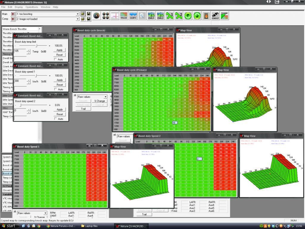
To keep it simple, we copied the values between primary/knock, and speed1/speed2 tables.

We started by trying to get a flat 1.1 bar all the way through the rev range in 4th and 5th gears. Hence the way speed 1/2 tables the way they are. It still drops off boost top end cos the turbo is totally maxxed.

We then tried mapping boost in 3rd gear.. now here was the problem. I would accelerate WOT from 2800rpm, and it would smoothly go to 0.8bar and creep to 1bar by around 5k. BUT if I let off the accelerator for a few seconds, and then gave it WOT at say 4.5k, it would immediately spike up to 1.4bar before hitting the load cut. Is there a reason why it would be doing that? Software or hardware? (there is a small possibility it was my mate doing something accidentally - he was doing all the mapping while I was driving). It still held 1bar perfectly in gears 4 and 5.

Here are all the settings we ended up with tonight. There is no excessive spiking, but ive only got 0.8bar max in midrange 3rd gear.
Image

I dunno if this helps anyone, I think I have more questions than answers TBH. If anyone could enlighten me as to exactly how the in-gear boost system works, that would be great.

Cheers
Matthew
Matt
Site Admin
 

Posts: 8993
Joined: Sun Jan 29, 2006 1:45 am
Location: Adelaide, Australia
Contact:

Re: Boost control on s14 SR20DET

Post by Matt »

Likely the spike is something in the Nissan ECU firmware (some corner condition). The tables we went through by looking at the speed registers and finding limits checked. We mapped it all out for the S15 that AT/MT tables are different also but S14A needs another look
Munkul333
 

Posts: 21
Joined: Wed Nov 28, 2012 9:55 am

Re: Boost control on s14 SR20DET

Post by Munkul333 »

I will have to take some logs to see exactly what the solenoid duty is doing in relation to the tables.

Ideally I'd get it mapped for the same boost in every gear, and only bother fiddling with low gear boost later on.

Is there a high gear switch on s14a ECUs? There are two switches on the box itself as well as the speed sensor, but I thought they were for neutral and reverse....? If we can get it set properly to road speed it would be much better for drag launches/low speed corners... 3rd gear hooks up not too bad anyways so it would ideally have full boost like 4th and 5th...
Matt
Site Admin
 

Posts: 8993
Joined: Sun Jan 29, 2006 1:45 am
Location: Adelaide, Australia
Contact:

Re: Boost control on s14 SR20DET

Post by Matt »

There is no high gear switch going into the ECU. If you can post the logs I can look at it during down time
Munkul333
 

Posts: 21
Joined: Wed Nov 28, 2012 9:55 am

Re: Boost control on s14 SR20DET

Post by Munkul333 »

This is the oddest thing ever, I know like you say there is no high gear switch, but maybe it works it out itself from rpm vs speed?

Look at this log, I will attatch my bin as well for comparison to boost tables. (speed2 table is back up to the working duty cycle, but during this log the highest values were set to a flat 10%)

It gives a solenoid duty of 50-60% right until 4th gear, where it flat-lines at 10% (just as I had set speed2). It doesnt seem to matter what you do with the other tables, in 4th/5th it solely reads from speed2. Also, every time i try to set boost duty speed 2 from anything other than 0, it resets itself to 0 as soon as you close the window.

This would be SO useful if we could get the speed2 limit working, and lower it enough to include 3rd gear.

Anyone else got any input on what the other tables do? I should have tried lowering each table in turn to see what effect it had on duty cycle, but I was running low on fuel, lol

Also I know, I need a stronger actuator, I think that's what I need cos it's spiking as bad if not worse than it did on my MBC.
Attachments
s2 low_2013-02-21_2245_03.csv
(149.88 KiB) Downloaded 274 times
boost not bad.bin
(64 KiB) Downloaded 299 times
Munkul333
 

Posts: 21
Joined: Wed Nov 28, 2012 9:55 am

Re: Boost control on s14 SR20DET

Post by Munkul333 »

Matt? No reply? Speed2 is non-adjustable, speed1 doesnt appear to affect anything.
Matt
Site Admin
 

Posts: 8993
Joined: Sun Jan 29, 2006 1:45 am
Location: Adelaide, Australia
Contact:

Re: Boost control on s14 SR20DET

Post by Matt »

Sorry but its something I need to allocate time for and plug on the bench and look into and then go through the code again. Its not something I can just jump into whilst browsing the forums. I've noted it down to investigate
Matt
Site Admin
 

Posts: 8993
Joined: Sun Jan 29, 2006 1:45 am
Location: Adelaide, Australia
Contact:

Re: Boost control on s14 SR20DET

Post by Matt »

Okay tested S15 SR20DET (AT model) tonight

- Speed < 46KM/h will use the primary boost control map
- Knock sensor fault triggered will use the knock boost control map (will not use the speed1/2 maps)
- Speed > 46KM/h will use the speed 2 boost control map

With speed = 46 km/h
- Adjust speed 2 to 56 km/h and will switch to speed 1 control map
- Adjust speed 1 to 51 km/h and will switch to primary boost control map

This means on S15 that all parameters work as expected. Might be different for S14A (TBD)

Also for interest sake more fixes required: ER34 the boost maps are not TPS based but are TP based (verified using hardware maptracing) and VE maps are TPS based (not TP based)
Matt
Site Admin
 

Posts: 8993
Joined: Sun Jan 29, 2006 1:45 am
Location: Adelaide, Australia
Contact:

Re: Boost control on s14 SR20DET

Post by Matt »

Another followup reply. S14A is same as S15... but it depends on your transmission type

S14 AT image tested 80F10 will jump to speed1/2 maps dependent on speedo input but 80F00 will say on the main/knock boost maps

Only auto transmission models use the speed1/2 maps. I split the S15 address files up because of this. Wondering if I should do the same for S14? The main reason for S15 is that injector base sizes are different. Perhaps I'll just rename the speed tables to AT only
Munkul333
 

Posts: 21
Joined: Wed Nov 28, 2012 9:55 am

Re: Boost control on s14 SR20DET

Post by Munkul333 »

Thanks for taking some time to look into it.

I am using 82F00 base image although my ECU and nistune board base image may not match... fairly sure my ecu is a 74F00... both are M/T but I used an s14a ECU to rob the nistune board out of for my s14 that had the s14a style loom plug... this was before I new about all the different base images etc! Only issue is that if i try to tune on the 82F00 image before connecting and syncing up, it tells me its incompatible, I have to sync down the map from the ECU each time and tune on that.
Everything else works just fine, though.

If you look at the log I attached, it proves that the boost duty is not dependant on speed - I've put into a graph form witha couple of annotations to show you what I mean.
Plus, this is with speed1/speed2 set at 300/0 respectively, with speed2 setting itself to 0 regardless of what I try.

I will take some more logs soon but for now I've went back to an MBC for better spool. I'd still love to get this working properly for drag racing, though.
Attachments
boost duty cycle graph.xls
(448 KiB) Downloaded 233 times
Matt
Site Admin
 

Posts: 8993
Joined: Sun Jan 29, 2006 1:45 am
Location: Adelaide, Australia
Contact:

Re: Boost control on s14 SR20DET

Post by Matt »

If you want to monitor the boost duty properly:

Code: Select all

0x5FD5:  9C 62 30 00 F0          ldm    #HIGH_BOOST_DUTY,0x3062
0x5FDA:  2C BA 30 01 00 23       bbs    #0x0001,0x30BA,0x6003
0x5FE0:  2C BA 30 02 00 1D       bbs    #0x0002,0x30BA,0x6003
0x5FE6:  2C BA 30 04 00 07       bbs    #0x0004,0x30BA,0x5FF3
0x5FEC:  9C 62 30 00 F1          ldm    #REG_BOOST_DUTY,0x3062
0x5FF1:  80 10                   bra    0x6003

0x5FF3:
0x5FF3:  9C 62 30 20 F6          ldm    #BOOST_DUTY_SPEED1,0x3062
0x5FF8:  3C BA 30 08 00 05       bbc    #0x0008,0x30BA,0x6003
0x5FFE:  9C 62 30 20 F7          ldm    #BOOST_DUTY_SPEED2,0x3062

0x6003:
0x6003:  9C 64 30 00 F4          ldm    #RPM_SCALE_BOOST_DUTY,0x3064
0x6008:  9C 66 30 10 F4          ldm    #TP_SCALE_BOOST_DUTY,0x3066
Display > RAM tracer
Monitor address 30BA (length = 1)

If the value contains X1 or X2 then will use High boost
If the value contains X4 then will use speed1
If the value contains X8 then will use speed2
If the value is none of the above the Reg boost table is used

Your image 82F00 is manual transmission which should not use the speed1/speed2 setting

I'm adding code at the moment to monitor this 30BA memory address and highlight the corresponding boost map on the left list of tables as I write
Matt
Site Admin
 

Posts: 8993
Joined: Sun Jan 29, 2006 1:45 am
Location: Adelaide, Australia
Contact:

Re: Boost control on s14 SR20DET

Post by Matt »

Also S14A used Type 4 board (80Fxx, 82Fxx, 83Fxx) whilst S14 uses Type 3 board (74Fxx, 75Fxx). Make sure you use the correct base image!
Munkul333
 

Posts: 21
Joined: Wed Nov 28, 2012 9:55 am

Re: Boost control on s14 SR20DET

Post by Munkul333 »

Matt wrote:Also S14A used Type 4 board (80Fxx, 82Fxx, 83Fxx) whilst S14 uses Type 3 board (74Fxx, 75Fxx). Make sure you use the correct base image!
Hmm. I wasnt aware of the board type differences either, when I swapped the board into my own ECU. So that means that not only is the base image wrong, but the board type itself is wrong too...

...well so far it's tuned really easily in all the important areas as long as i keep the tune synchronized between ECU and laptop, and these differences are only coming to light just now so I must have just got REALLY lucky :lol:

So, out of interest, does the 74F00 ECU use speed1/speed2?

I'm guessing that the base image differences are the reason why I'm having problems setting the boost-speed parameters.
Matt
Site Admin
 

Posts: 8993
Joined: Sun Jan 29, 2006 1:45 am
Location: Adelaide, Australia
Contact:

Re: Boost control on s14 SR20DET

Post by Matt »

74F00 wont use the speed 1/2 parameter because that is a manual transmission model. As I posted before, these tables are only used with AT models as verified with hardware map tracing equipment on the bench

It looks at the feedback flags AT parameter to decide if to use the speed 1/2 tables

Code: Select all

; check feedback flag for trans type
0x609D:  2C 38 E0 80 17          bbs    #0x80,FB_SWITCH,0x60B9 ; check MT

AT:
0x60A2:  AD D4 30                lda    al,VEHICLE_SPEED
0x60A5:  CD 70 F4                cmp    al,BOOST_DUTY_SPEED_LIMIT1 (46km/h)
0x60A8:  90 3A                   bcc    0x60E4 (speed > limit) skip

0x60AA:  0C BA 30 04             seb    #0x04, 0x30BA (BOOST_FLAG) (#speed1 flag)
0x60AE:  CD 71 F4                cmp    al,BOOST_DUTY_SPEED_LIMIT2 (0km/h)
0x60B1:  90 31                   bcc    0x60E4 (speed > 0km/h limit)
0x60B3:  0C BA 30 08             seb    #0x08, 0x30BA (BOOST_FLAG) (#speed2 flag)
0x60B7:  80 2B                   bra    0x60E4

MT:
0x60B9:  42 AD DA 30             lda    bl,0x30DA 
0x60BD:  AD D9 30                lda    al,0x30D9
0x60C0:                          

Knock flags check:
0x60E4:
0x60E4:  3C AF 30 80 06          bbc    #0x80,0x30AF,0x60EF (knock flag set?)
0x60E9:  0C BA 30 02             seb    #0x02, 0x30BA (BOOST_FLAG #boost knock)
0x60ED:  80 04                   bra    0x60F3

Knock flag clear:
0x60EF:
0x60EF:  1C BA 30 02             clb    #0x02, 0x30BA (BOOST_FLAG #boost high)
Matt
Site Admin
 

Posts: 8993
Joined: Sun Jan 29, 2006 1:45 am
Location: Adelaide, Australia
Contact:

Re: Boost control on s14 SR20DET

Post by Matt »

Further testing tonight shows the definitions above and the tables in Nistune have the boost / knock boost tables backwards. If I clear the knock fault the highlighting shows the knock table when it should be showing the main table. I'll reverse these for the next software build (affecting S14/S14A only S15 was fine)
Post Reply